SPP A-pillar pod and Omori 60mm boost gauge install

Got Boost?
Well, after over a year with the GIAC chip, I finally decided to install a boost gauge! :-) I
opted for the 60mm Omori gauge from Omori Meter in Japan
(I bought the whole setup off a friend, tho). I went with 60mm because it
had the Peak/Hold/Warning feature. Also, this gauge has red lightning with a
white needle -- matches the S4 dials VERY WELL! This pod will live inside
the Supreme Power Parts
(SPP) integrated A-pillar pod (60mm, of course).
Starting out...
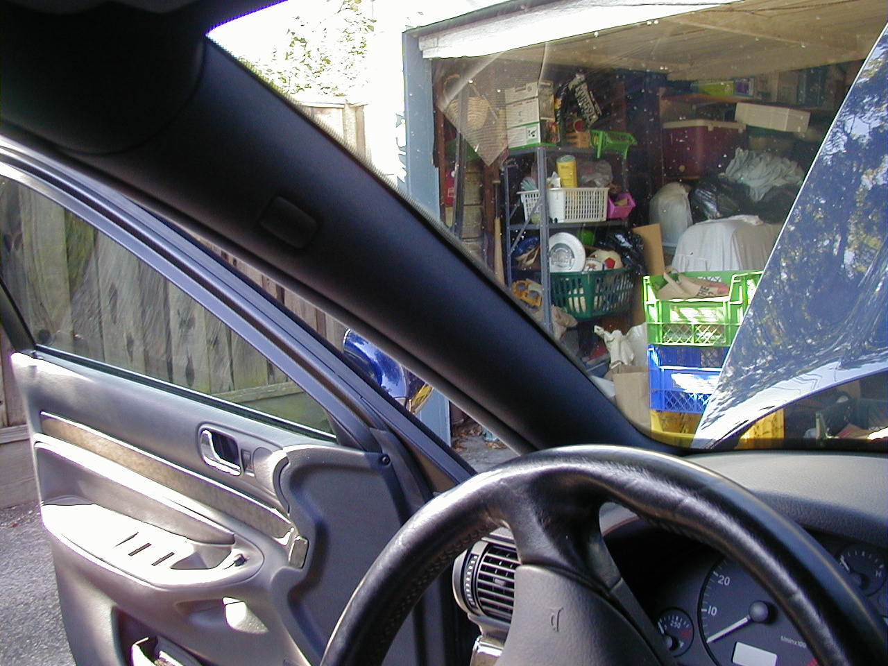
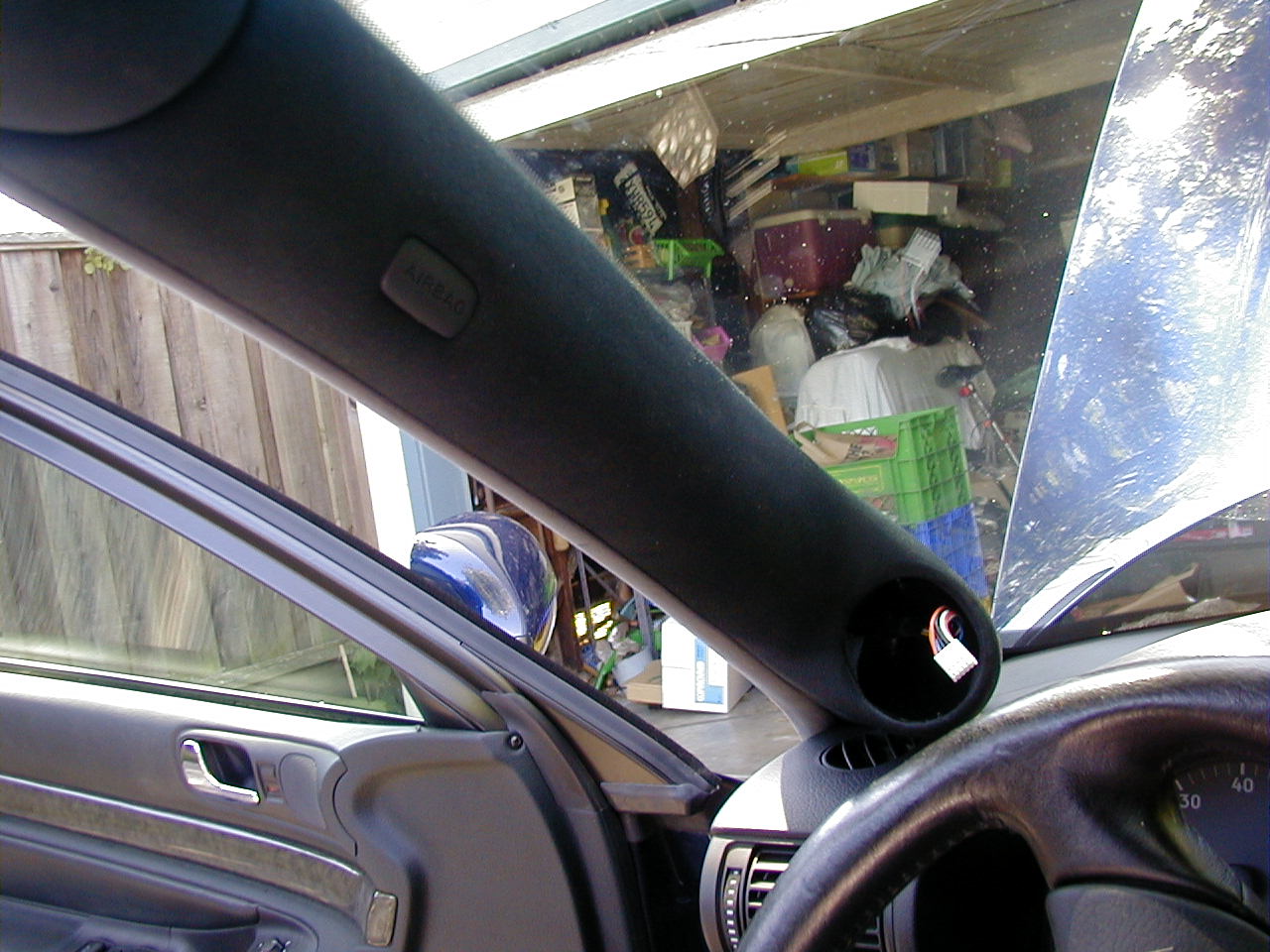
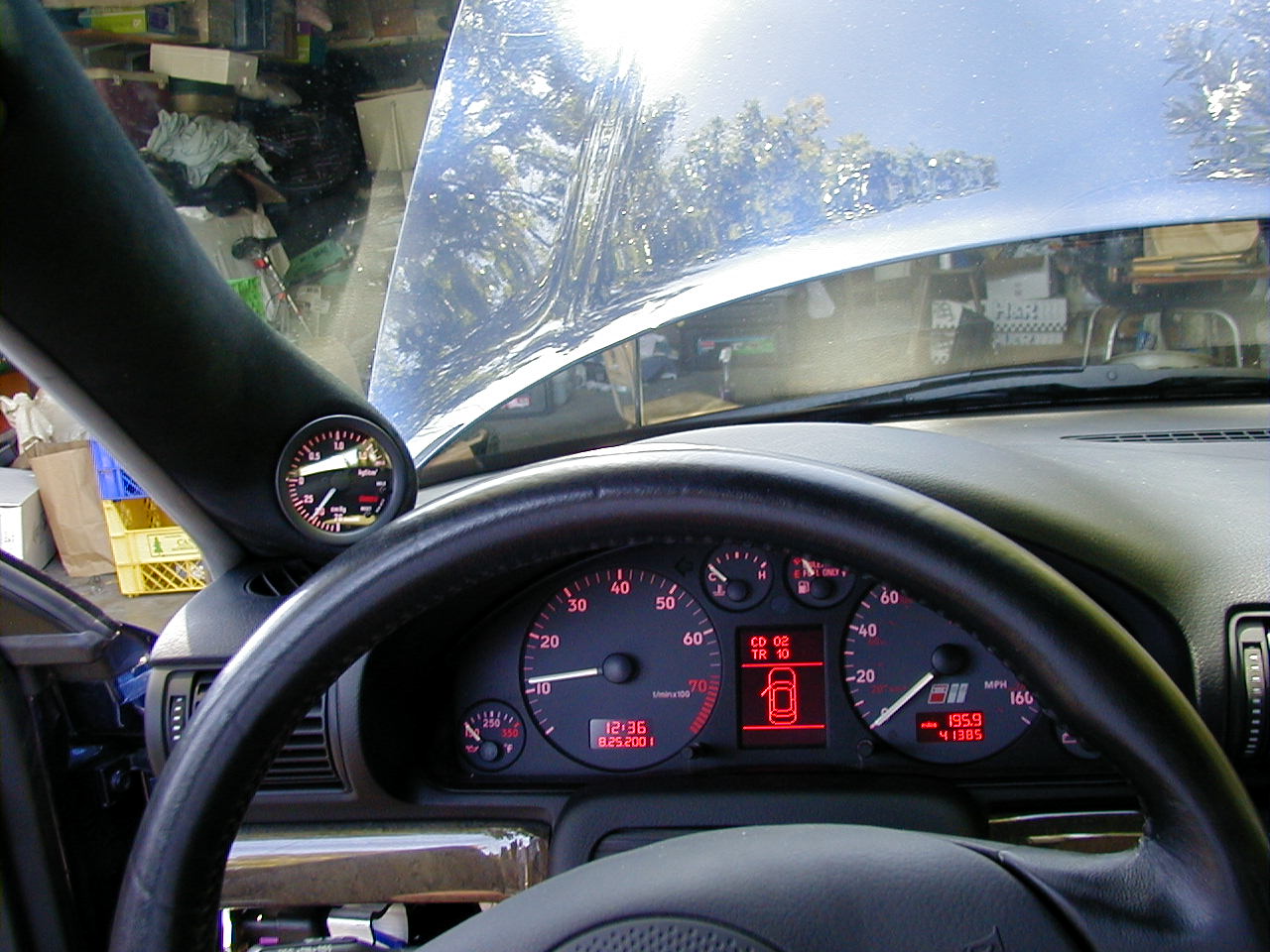
 [LEFT]Well, here's a shot of the stock A-pillar - before the operation... Please
ignore the messy garage! ;-)
[LEFT]Well, here's a shot of the stock A-pillar - before the operation... Please
ignore the messy garage! ;-)
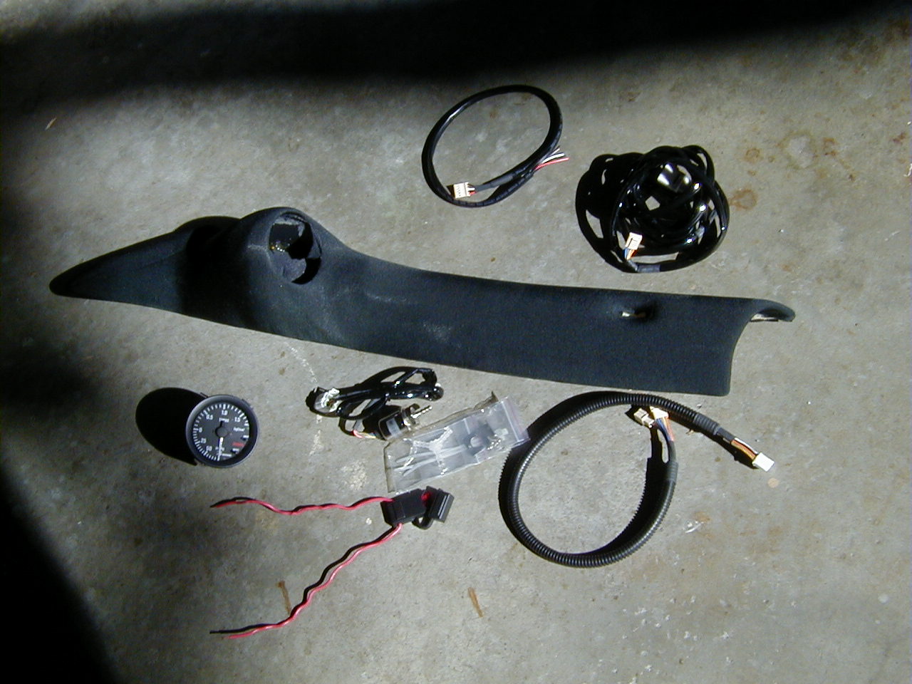
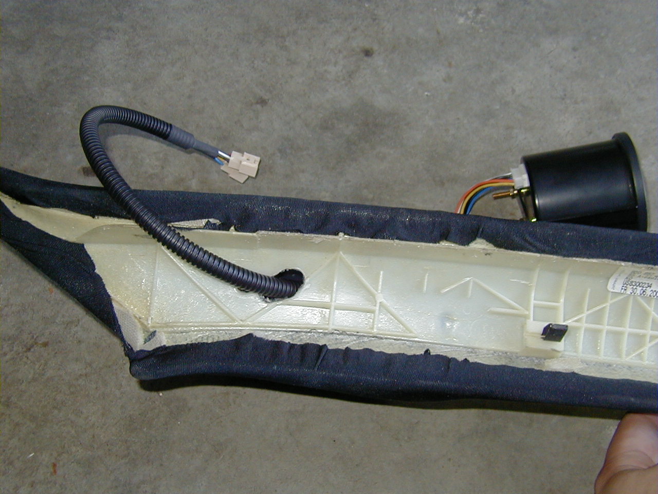
[RIGHT]The goods! Here we have all the goods: SPP 60mm a-pillar pod, 60mm Omori
electrical boost gauge, inline blade-type fuse (w/ 10amp fuse), pressure
sensor (the cylindrical metal thing that looks like a small RC-car motor),
various wiring harnesses, boost line Tee and pressure sensor mounting
hardware.
PARTS:
TOOLS:
The Operation...
 Ok, After removing the ECU cover, and the ECU, itself, I removed the little
"nipple" of rubber that is just above the accordianated rubber tube that
comes out of the front of the ECU box. I had to cut this off with a razor
blade, and then I sort of cut into the rubber around the hole, to make it a
little bit bigger. I still left it small enough so that the vacuum line
would be snug when passing thru the rubber grommet.
Ok, After removing the ECU cover, and the ECU, itself, I removed the little
"nipple" of rubber that is just above the accordianated rubber tube that
comes out of the front of the ECU box. I had to cut this off with a razor
blade, and then I sort of cut into the rubber around the hole, to make it a
little bit bigger. I still left it small enough so that the vacuum line
would be snug when passing thru the rubber grommet.
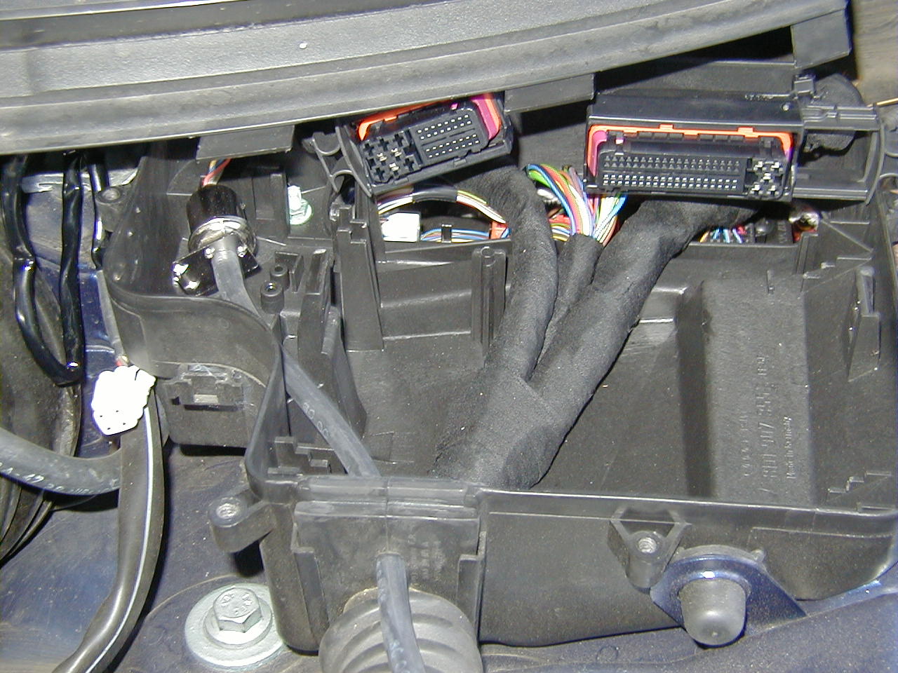
Notice the pressure
sensor on the upper left, I mounted it just about where you see it, slightly
above. I used a super-small drill bit to drill pilot holes for the screws,
but you could have just as easily used an awl or something to poke holes.
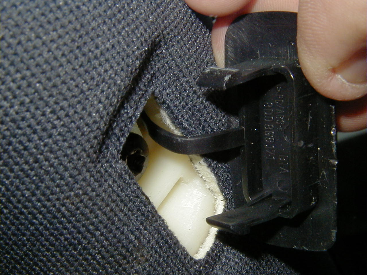 Next, I went inside to remove the A-pillar, itself. You must first pop off
the 'AIRBAG' logo. Simply pry it out w/ a flathead screwdriver, but notice
how it is attached from the top (well, kind of). Just be careful, but you
may need to use a decent amount of force to remove it (at least, I did).
Next, I went inside to remove the A-pillar, itself. You must first pop off
the 'AIRBAG' logo. Simply pry it out w/ a flathead screwdriver, but notice
how it is attached from the top (well, kind of). Just be careful, but you
may need to use a decent amount of force to remove it (at least, I did).
 Once that is removed, you'll need a T-25 Torx to remove the single screw
beneath the 'AIRBAG' logo. After removing said screw, simply pull the
A-piller cover off (slowly, carefully, tho!). You may hear what sounds like
tearing, but there appears to be velcro on the bottom side, and the top side
(near the glass) may be stuck to the gunk they use to adhere the windsheld.
Never fear, just continue to pull it off (first just directly away from the
A-pillar, and then up and out from the corner).
Once that is removed, you'll need a T-25 Torx to remove the single screw
beneath the 'AIRBAG' logo. After removing said screw, simply pull the
A-piller cover off (slowly, carefully, tho!). You may hear what sounds like
tearing, but there appears to be velcro on the bottom side, and the top side
(near the glass) may be stuck to the gunk they use to adhere the windsheld.
Never fear, just continue to pull it off (first just directly away from the
A-pillar, and then up and out from the corner).
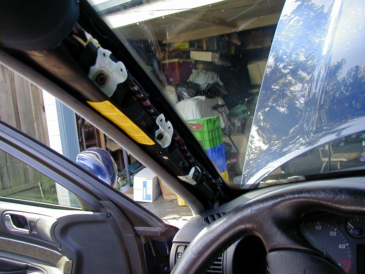 Once removed, this is what you see... ugly, eh? ;-)

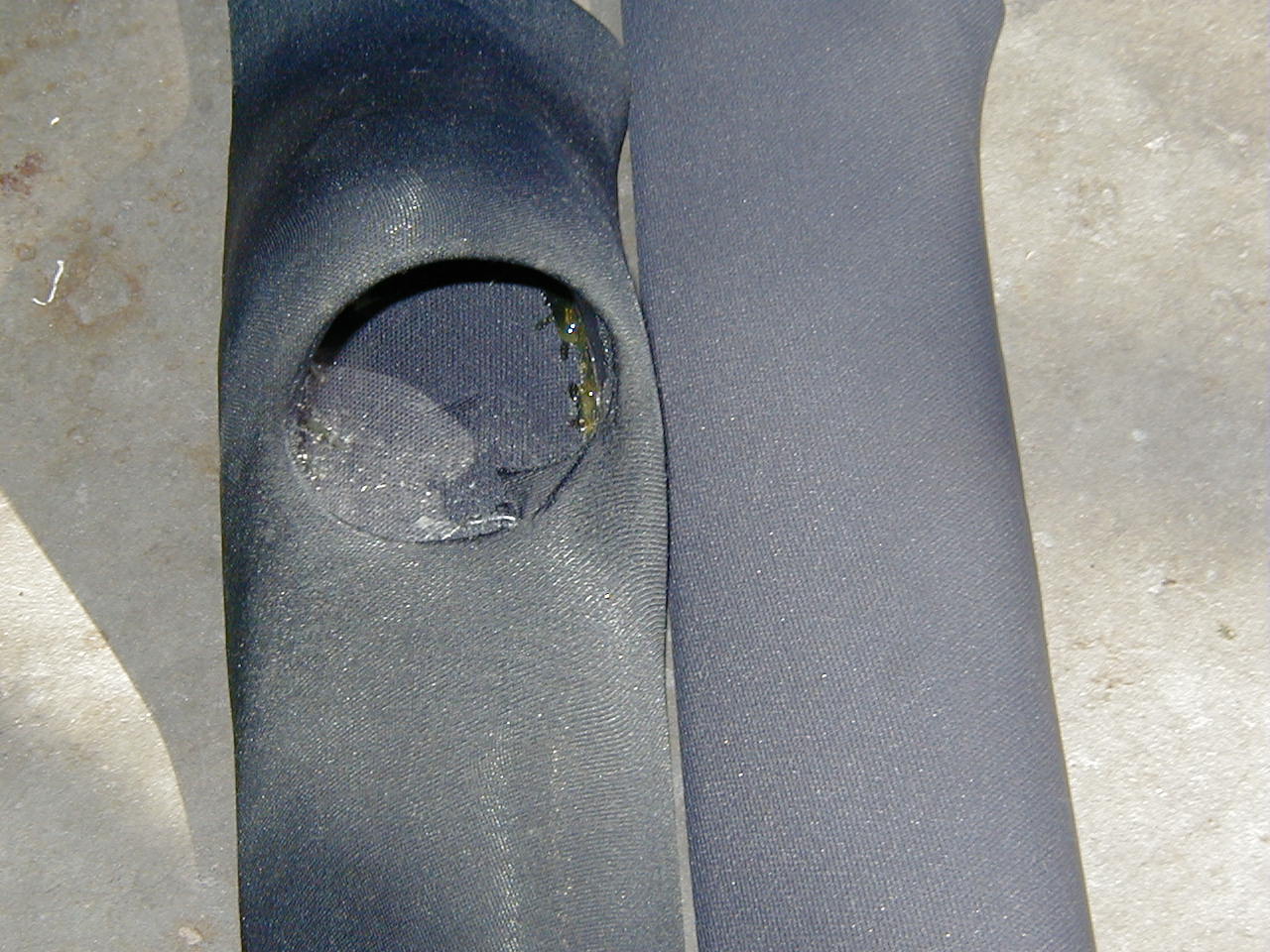 Here are 2 pics, trying to capture the color difference of the pillar cloth.
The SPP pillar is noticeably darker (more black).
Here are 2 pics, trying to capture the color difference of the pillar cloth.
The SPP pillar is noticeably darker (more black).
 Silly me, I got so caught up in what I was doing, that I forgot to take
pictures of removing the lower kick-panel from the driver's-side footwell.
But I've gone back and taken pictures, and I'll explain it as best as
possible.
Silly me, I got so caught up in what I was doing, that I forgot to take
pictures of removing the lower kick-panel from the driver's-side footwell.
But I've gone back and taken pictures, and I'll explain it as best as
possible.
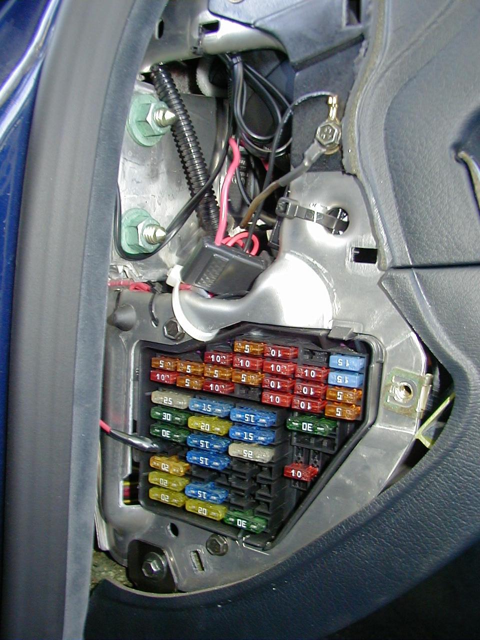
First, pop off the fuse cover (use a flathead screwdriver).
 Next, remove the bolt that is visible at the BOTTOM of this picture.
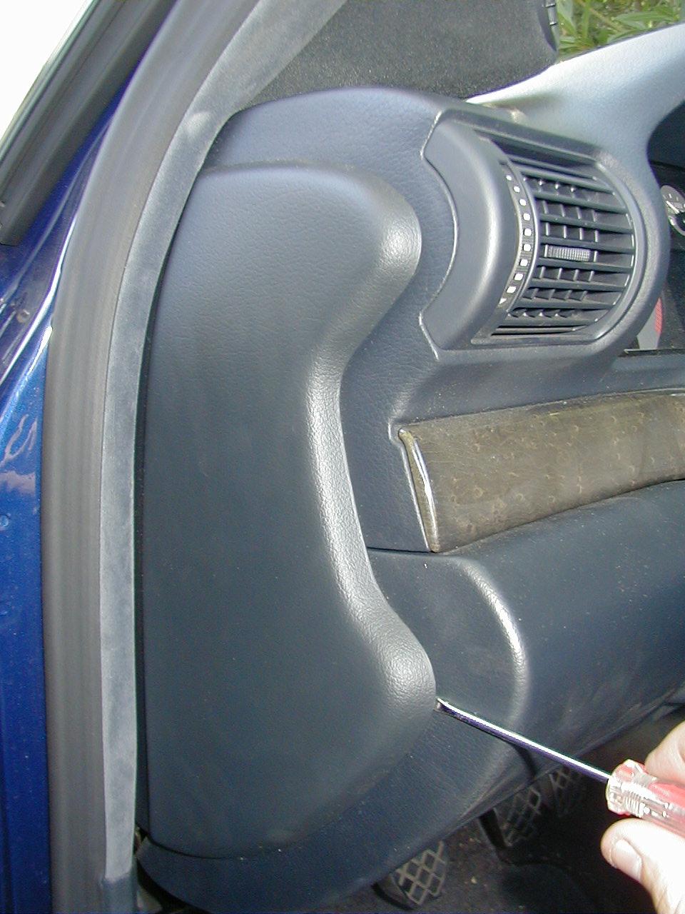
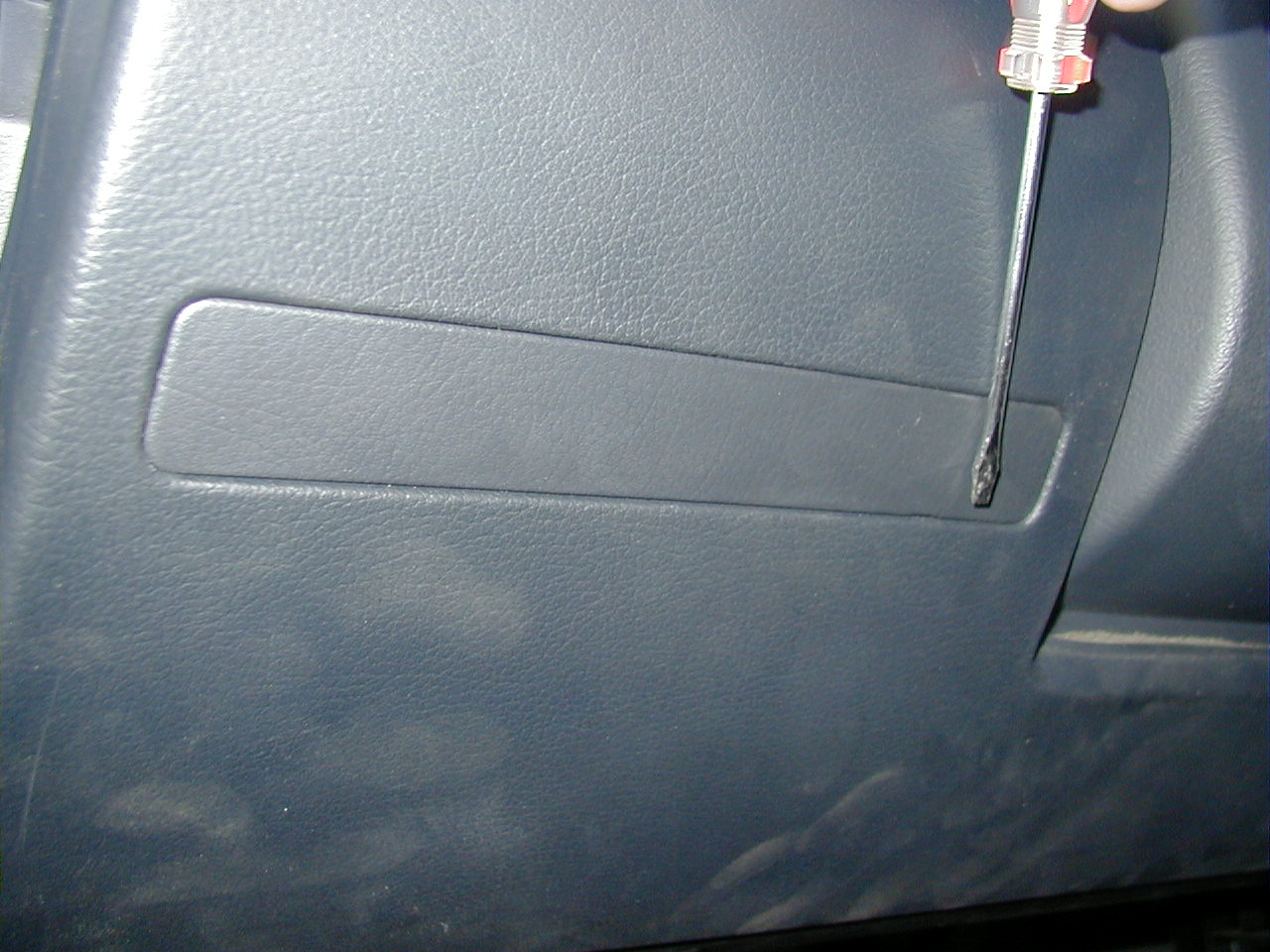 Then, pop off the rubber/plastic cover seen here, and remove the bolt that is
just about where the screwdriver head is.
Then, pop off the rubber/plastic cover seen here, and remove the bolt that is
just about where the screwdriver head is.
(yes, it's dirty as heck, my whole car is... needs a bath, badly...:-()
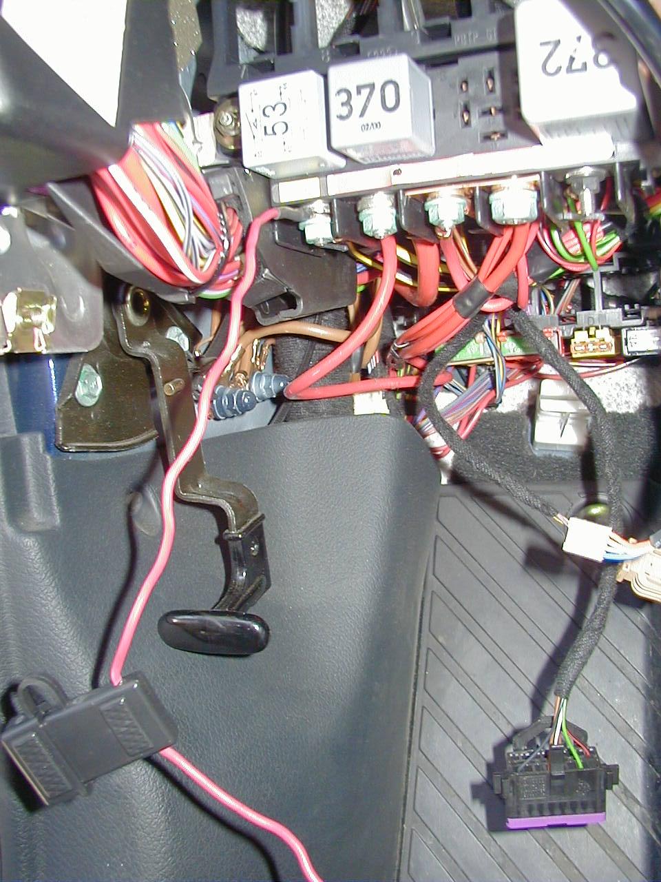
 Now the right side - I've removed the plastic/rubber cover for show.
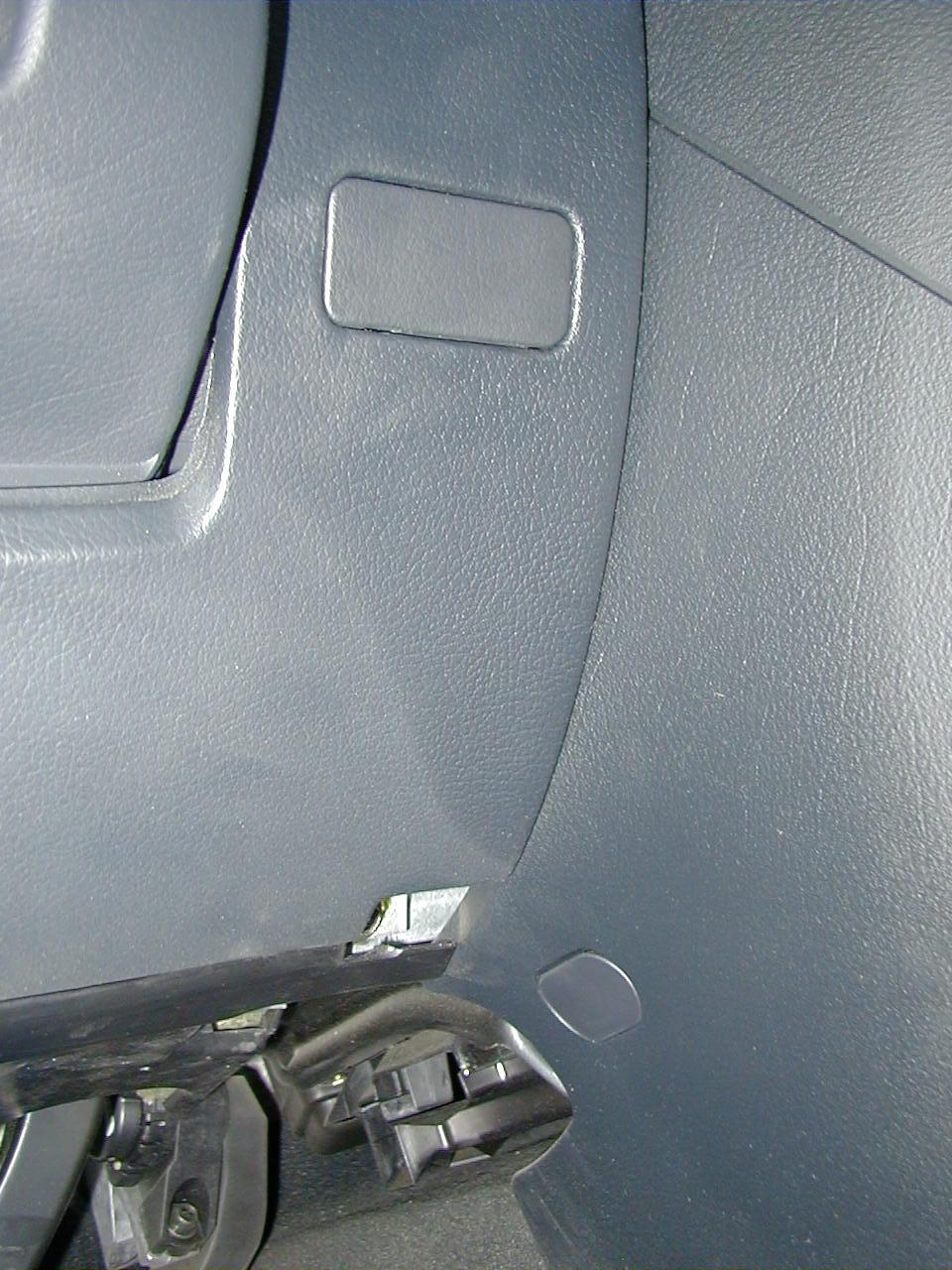 The last bolt is where the silver spot is, towards the bottom of this
picture. Don't forget to remove it, too! I almost did, and was wondering
why it was so hard to get the kickpanel off! ;-)
The last bolt is where the silver spot is, towards the bottom of this
picture. Don't forget to remove it, too! I almost did, and was wondering
why it was so hard to get the kickpanel off! ;-)
OK, no pics now, I didn't feel like disassembling my car again ;-)
To
remove the kickpanel, just pull it down slightly, and then before pulling it
out, disconnect the OBD-II connector (squeeze the tabs) and the
floorlight power (give it a pull, or
wiggle-back-and-forth-until-the-bugger-comes-out action ;-).

 Left pic - flash, near focus
Right pic - no flash, far focus
Here are a couple pics looking into the ECU container that shows how it goes
right thru into the footwell area! :-) Notice the tools (right-side pic)
:)
Anyway, feed the end of the harness that runs from the boost pressure sensor
to the gauge down thru this hole, and fish it out from the other side.
 Next, I wanted to make all the electrical wiring neat, so I opted to solder
and use shrinkwrap over the joints. The two black wires I soldered together, and then to a
connector. The red and white were soldered together and then to the
inline fuse holder, which was then soldered to another connector. The brown wire was folded back onto itself with a piece
of shrinkwrap sealing it off, and stuffed back into the harness sheath.
Next, I wanted to make all the electrical wiring neat, so I opted to solder
and use shrinkwrap over the joints. The two black wires I soldered together, and then to a
connector. The red and white were soldered together and then to the
inline fuse holder, which was then soldered to another connector. The brown wire was folded back onto itself with a piece
of shrinkwrap sealing it off, and stuffed back into the harness sheath.
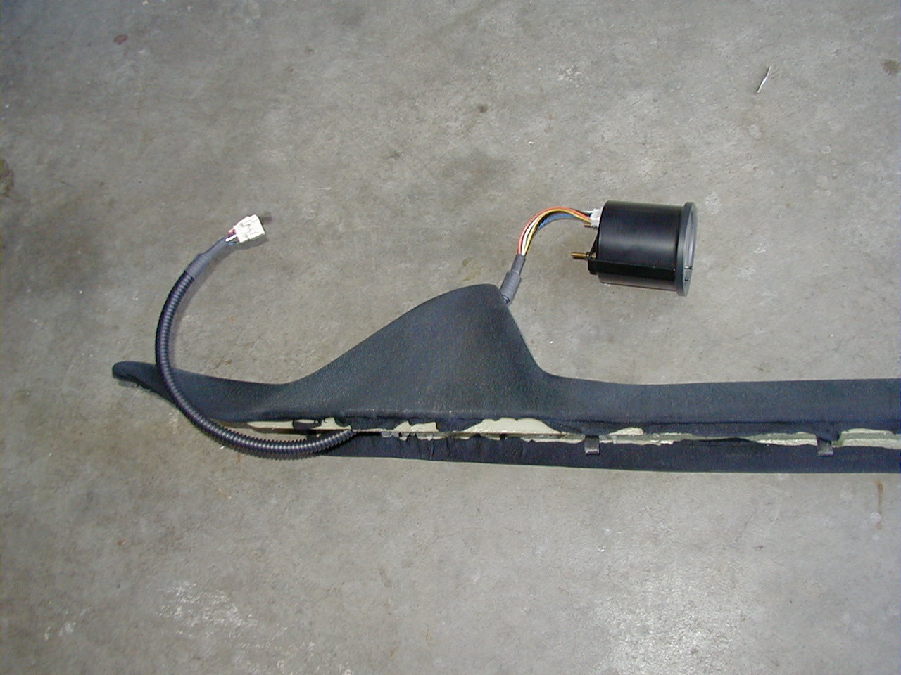 Here's the gauge w/ its harness attached
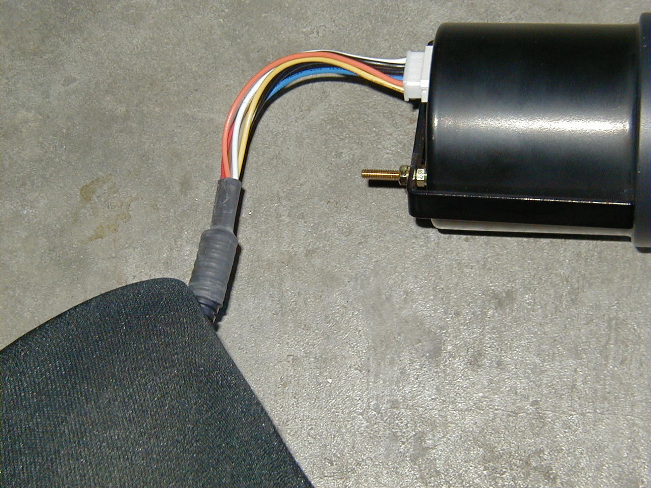 A closeup -- when you get your Omori gauge, the black harness sheath is much
closer to the end connector than mine is now (look at the 2nd pic, way up
top). I simply pulled the shrinkwrap back off it, and cut it back, and then
worked the shrinkwarp back on it :)
A closeup -- when you get your Omori gauge, the black harness sheath is much
closer to the end connector than mine is now (look at the 2nd pic, way up
top). I simply pulled the shrinkwrap back off it, and cut it back, and then
worked the shrinkwarp back on it :)
This was done so that there will be more slack on the wires when I cram it
all into the pod :)
 Another view.
 Now, disconnect the gauge -- it's much easier to install the pillar w/o extra
weight of the gauge in there ;-)
Now, disconnect the gauge -- it's much easier to install the pillar w/o extra
weight of the gauge in there ;-)
This was a tough part for me -- getting the piller back on... lots of
grunting and pushing... but eventually is will go on :) Just try to align
the clips ahead of time, and look for the marks the old A-piller left, and
try to line those up, as well :)
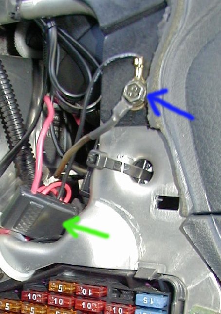 Ok, now for the wiring. Attach the power connector to the 75X terminal (far
left). Attach the other one to ground. I used the bolt identified with the
blue arrow in the pic to the right (near fuse
panel). The green arrow denotes where I ended
up putting the inline fuse holder (held in place by a ziptie).
Ok, now for the wiring. Attach the power connector to the 75X terminal (far
left). Attach the other one to ground. I used the bolt identified with the
blue arrow in the pic to the right (near fuse
panel). The green arrow denotes where I ended
up putting the inline fuse holder (held in place by a ziptie).
Now, tidily coil up the excess wiring harness and ziptie it somewhere (I used
the compression-absorbing aluminum honeycomb (you'll see what I'm saying once
you take off the kickpanel ;) to secure my wires to).
 Connect the gauge and stuff it into the pod, and you're done with that part!
:-)
Connect the gauge and stuff it into the pod, and you're done with that part!
:-)
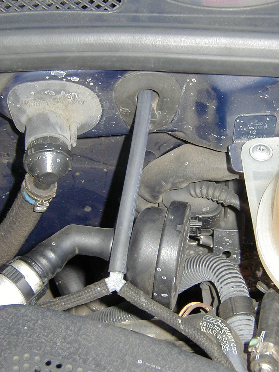 LAST, but by no means least, you need to splice into the vacuum line that
runs from the charge pressure sender to the fuel regulator. This is a
braided line as seen on the left. Use copious spit on the T-connector and
work it into the vacuum line slowly. Oh, I poked a hole in the grommet, as
you can see (just cut away slowly with a razor, until I could SNUGLY pass the
vacuum line thru)
LAST, but by no means least, you need to splice into the vacuum line that
runs from the charge pressure sender to the fuel regulator. This is a
braided line as seen on the left. Use copious spit on the T-connector and
work it into the vacuum line slowly. Oh, I poked a hole in the grommet, as
you can see (just cut away slowly with a razor, until I could SNUGLY pass the
vacuum line thru)
BTW, please ignore the white spots in this pic - they are from a massive coolant
leak I just discovered (wonderful!) *sigh*
Welp, that's about it... I checked all my connections, etc, and then buttoned
everything back up!
Testing it out...
Well, I took the car out for some sprints, and all seems to be operating
well!
CLICK HERE FOR MORE PICS!!
P.S., thanks for ryan@s4.org and LosGatosS4 for initial help/pointers! :-)